
General

In gutters and pipes of normal dimensions (up to 5″) the power required is calculated to 30 W/m gutter/pipe. In box gutters and other wider valleys you have to apply the cable in several runs to obtain the power required. When calculating the power required for this type of applications the rule of thumb are 250 – 300 W/m². If a total melting and drying up is not necessary the cable can be applied in 4 runs in the middle of the gutter with a c/c-distance of 30-40mm. If the gutter is angular, one run is applied in each corner to avoid frost erosion.
To keep bigger areas on roof applications free from snow and ice the power required is calculated to 30 W/m².
How to choose type of cable
Which type of application to choose (TCPR or SAFE-T) is often a question of economy.
Whichever type you choose, with the correct dimensioning, you will obtain the power required. When choosing cable the following should be taken into consideration:
If all gutters, pipes and other areas on the roof, where heating cable is to be applied, are measured, you can decide upon the lengths of the lengths and then it is easy to design a cost effective and well-functioning application with the TCPR-cable.
If you do not know the exact proportions of the application in advance, it is better to choose the Safe-T cable considering the total cost – material and work. This cable type are sold by the metre together with a suitable number of cable connectors and termination kits to buy cut and applied directly on the site.
Self-Limiting cable
DESIGNING ROOF APPLICATIONS WITH SELF-LIMITING HEATING CABLE (SAFE-T)

SAFE-T is a self-limiting heating cable in which the output is depending on the temperature of the cable. At an ambient temperature of 0°C in ice/snow this heating cable delivers 36 W/m. At the same temperature, but in air, it delivers 18 W/m. The output of the cable goes towards 0 at a rising temperature (65°C).
With these qualities this cable is a very good alternative when constructing roof applications.
Advantages:
- The SAFE-T cable has all the advantages a parallel resistive cable can have and in addition:
- The SAFE-T delivers power only when it is needed. (36 W/m in ice/snow).
- The SAFE-T can be cut in the exact length required (no zone-length to think of).
- The SAFE-T-applications are very easy to design and install.
- The SAFE-T can be connected directly in a control point.
- The SAFE-T can be applied directly on a surface coating of roofing card-board design basis.
Dimensioning roof applications with SAFE-T
Considering the max. permitted heating cable length – please see in the data sheet – the Velox Safe-T can be connected in several different ways.
- Add up the lengths of the gutters and pipes where heating cable is to be laid.
Please note! If the down pipes are connected to a ground surface drainage the heating cable must go down to a depth free from frosts to guarantee the outflow of water.
Add the length needed for the connection to the control point and 1 meter for each branching.
Example:…………………..m BTL SAFE-T
- Put together the requirement of junction boxes. All connections and branchings are done in standard cabinets.
E 14 396 02 (2 pcs glands)
E 14 396 04 (3 pcs glands)
E 14 396 10 (4 pcs glands)
E1439602……….st E1439604………..st E1439610……….st - Accessories:
Number of connection and termination kits (1 per length of cable)
Suspension hook (1 per down pipe)
Example: ……….. pcs cable connectors and termination kits
……….. pcs suspension hooks - Safety device: fuser, sizes of fuses.
Max. cable lengths for SAFE-T when starting up in ice/water (0°C)
Delay action fuses (characteristics D)
10 A 37 meter
16 A 59 meter
20 A 74 meter
The voltage drop in the conductors gives a 10% power drop out at 57m cable.
PLEASE NOTE! The regulations require earth-leakage-circuit-breakers 30mA.
Gutters/Wide valleys
Box gutters and wide valleys
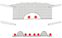
When installing heating cables in box gutters and valleys it is important that the power installed is so high that the heating cable really is able to melt all the snow that might surround it. At too low power there is a risk that a tunnel might be built up around the heating cable. This can result in the heating cable not being of any use although it is operating and consuming power. Furthermore the risk of ice-formation and falling snow remains.
An example shows how to apply heating cables in wide valleys and box gutters. This type of application does not produce a total melting away of the valleys, but it drains the gutter and protects against frost damage.
The fundamental rule is, when applying TCPR-cable in this type of gutters, that the cable is dimensioned to 20-25W/m and that the c/c-distance between the cables in the middle is 30-50mm.
The cable is applied according to the drawing with 4 runs of cable in the middle and with one run in each corner.
Dimensioning roof applications with series conductor heating cable (TCPR)
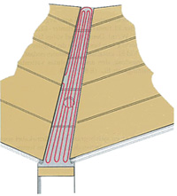 Valley
Example: A valley 12 m long and 350mm wide is to be applied with heating cable of type TCPR for drainage and frost protection. The valley has a roof well with an inside pipe in the middle.
By following the projecting step by step you can calculate how much cable will be needed and which cable resistance to choose.
Method of calculation:
- The length of the heating cable is decided (l).
- Required power per meter cable is decided (Pm).
- The total power (min/max) is calculated.
- The total resistance of the cable is calculated (Rt).
- Suitable cable resistance (Ohm/m) is chosen.
- Check calculations.
- The solution.
- Measure the entire length of the cable.
Example:
The valley: 6 x 12 m = 72m
Roof well: 2 x 1 m = 2 m
Extra for the short sides: 1m
Total length of cable: (l) 75m - Required power per meter cable (Pm)
20 – 25 Watt - Total power (Pt) = Pm x l
max 25 W/m x 75 = 1875 W
min 20 W/m x 75 = 1500 W - Calculation of the cable resistance: (Rt)
Ohms law for power R = U² / P
Rt min 230² / 1875 = 25.8 W
Rt max 230² / 1500 = 32.3 W - You now know that a heating cable of 75m is required and that its total resistance should be in the interval 25.8 – 32.3 Ohm. This means that the W/m value of the heating cable should be between 0.34 – 0.43 Ohm. From the TCPR-data sheet choose the cable resistance that is within the interval.
In our example we therefore choose TCPR 0.36 Ohm/m. - Check calculations:
The total power of the cable:
Formula: Pt = U² / Rt
Rt = The cables W/m x length.
Example: 230² / (75 x 0.36) = 1793 W
The power of the cable/m: Formula: Pm = Pt / l
Example 1793 ¸ 75 = 23.9 W/m - The solution: 75 m TCPR 0.36 Ohm/m
Total power: 1793 W
Power/m cable: 23.9 W
PLEASE REMEMBER! Problems with heating cables are never bigger than the distance to the nearest phone. Please contact VärmeKabelTeknik. We are ready to help you with design as well as deliveries of complete heating cable applications.
Gutters/Down pipes
Dimensioning roof applications with series conductor heating cable (TCPR)
Example: A gutter and the down pipes are to be applied with heating cable according to the sketch. The diameter in gutter and pipe is Ø 100 mm.
By following the projecting below step by step you can calculate how much cable will be needed and which resistance to choose.
Method of calculation:
- Power required watt per meter gutter/pipe is decided.
- The total length of the gutter and the pipe is measured.
- The length of the cable is decided (l).
- The required power (Pt) is decided.
- The suitable cable resistance is chosen (W/m).
- Check calculations.
- The solution.
- Power required: For gutters and pipes up to a diameter of Ø 125mm
30 – 50 W/m gutter
20 – 25 W/m cable. (Pm) - Measure the total length of all gutters and down pipes.
If the down pipes are connected to a ground surface drainage the heating cable should be put down about 1m below the ground level.If the down pipes are terminated with ejectors the length of the heating cable should be adjusted to come in touch with these. You generally calculate with the cable reaching about 100mm above the mouth of the down pipe.
Example: 5 + 15 + 4 + 1 = 25 meter.
- Heating cable length (l) = Length gutter + pipe x 2
Since the TCPR-cable is series resistive and without return-wire it will always be double-mounted in a special distance-clip which makes the cable length twice the gutter and pipe length.
Example: 25 x 2 = 50 meter. - The total power (Pt):
Pt = Pm x l
max 25 W/m x 50 = 1.250 W
min 20 W/m x 50 = 1.000 W - The resistance of the cable (Rt):
Ohms law for power R = U² / P
Rt min 230² / 1.250 = 42.3 W
Rt max 230 ² / 1.000 = 52.9 W
You now know that the heating cable of 50m is required and that its total resistance should be in the interval 42.3 – 52.9 Ohm. This means that the W/m value of the heating cable should be between 0.77 – 0.97 Ohm. From the TCPR-data sheet choose the cable resistance that is within the interval.
In our example we therefore choose TCPR 0.82 Ohm/m. - Check calculations:
The total power of the cable: Formula Pt = U² / Rt
Rt = the cables W/m x length.
Example: 230² / (50 x 0.82) = 1.290 W
The power of the cable/m: Formula: Pm = Pt / l
Example: 1.290 / 50 = 25.8 W/m - Result: 50 m TCPR 0.82 Ohm/m
Total power: 1.290 W
Power/m cable: 25.8 W
Power/m gutter: 47.2 W