POSITIONING AND ATTACHMENT

|
SPIRAL INSTALLATION
 Note Note
- If ratio of heater footage to pipe is greater than 1.5 – use two parallel heaters or select higher wattage heater. If ratio is less than 1.0 – use one parallel heater.
- When installing the heater on non-metal pipe secure the heater to the pipe with aluminium tape. Refer to pitch chart on isometric drawings for proper pitch length.
|
POWER CONNECTION KIT ◊ MOUNTING DETAIL ◊ ORDINARY AND HAZARDOUS AREAS
 Note. Note.
For more specific details and full materials list refer to installation instruction sheet packed with connection kit.
|
 END TERMINATION END TERMINATION
|
 THERMOSTAT SENSOR POSITIONING AND ATTACHMENT ON TANKS THERMOSTAT SENSOR POSITIONING AND ATTACHMENT ON TANKS
|
 POSITIONING AND ATTACHMENT OF THERMOSTAT SENSOR ON PIPE POSITIONING AND ATTACHMENT OF THERMOSTAT SENSOR ON PIPE
|
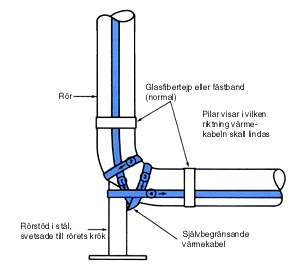
FÖRLÄGGNING AV VÄRMEKABEL VID RÖRKOPPLINGAR, VENTILER OCH PROCESSUTRUSTNING
 Note Note
 This detail is shown as an illustration of a method of taking advantage of the shape of a piping configuration to at-tain good pipe contact. To simply trace the inside radius of the corner would not be considered correct. Although a tee-splice might also be used to trace the third leg of the tee. The objective of this detail is to emphasize that it is advisable to get more heater on any area where the thermal insulation might not be fitted as well as on straight pipe. This method is intended to be used on other fittings besides tees. This detail is shown as an illustration of a method of taking advantage of the shape of a piping configuration to at-tain good pipe contact. To simply trace the inside radius of the corner would not be considered correct. Although a tee-splice might also be used to trace the third leg of the tee. The objective of this detail is to emphasize that it is advisable to get more heater on any area where the thermal insulation might not be fitted as well as on straight pipe. This method is intended to be used on other fittings besides tees.
|
FÖRLÄGGNING AV VÄRMEKABEL VID RÖRKOPPLINGAR, VENTILER OCH PROCESSUTRUSTNING
  Note. Note.
- Exact configuration may vary per valve type.
- For removable valve bodies leave a loop of tracing of the proper length when tracing the pipe.
- See installation chart for correct amount of tracing per valve size.
- Take care to keep the flat side of the heater in as good physical contact with the valve body as possible.
- Fully insulate and weather protect. .
|
HEAT TRACING OF FITTINGS, VALVES AND PROCESS EQUIPMENT

Note.
- See National Electrical Code paragraph 427-12(E).
 Fully insulate and weatherproof (if outdoors). Fully insulate and weatherproof (if outdoors).
Note. Heater must be pulled thru flexible conduit to avoid splicing – if necessary to splice heater a junction box will be required. |
HEAT TRACING AROUND PIPE SUPPORTS
  Note Note
All pipe supports must be fully insulated and weatherproof (if outdoors). |
  Note. Note.
All forms of rigid pipe supports directly in contact with the pipe surface act as a heat sink. Heat tracing should be doubled over at these points and the supports should be insulated as much as practicable to limit heat loss. |
HEAT TRACING OF LINE MOUNTED INSTRUMENTS
 
 
Note
Treat turbine flow meter as a valve of the same pipe diameter. Leave a loop of material the same as for a valve.
 
Notes:
1. Fully insulate and weatherproof.
2. Exact configuration may vary.
3. refer to installation isometrics for proper tracer type and amount.
4. Where the heater is applied in the region designated as “Bolt Area” aluminium tape should be used to aid heat transfer because of the excessively irregular surface.
 
|

 Note.
Note.

 Note
Note Note.
Note.


 Note
Note This detail is shown as an illustration of a method of taking advantage of the shape of a piping configuration to at-tain good pipe contact. To simply trace the inside radius of the corner would not be considered correct. Although a tee-splice might also be used to trace the third leg of the tee. The objective of this detail is to emphasize that it is advisable to get more heater on any area where the thermal insulation might not be fitted as well as on straight pipe. This method is intended to be used on other fittings besides tees.
 Note.
Note.
 Fully insulate and weatherproof (if outdoors).
 Note
Note


